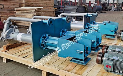
LYF Vertical Mud Pump is mainly used in mining systems such as pit pumps in coal preparation plants, slag and ash washing pit pumps in power plants, and pit pumps for flue gas desulfurization, to convey solid particles. Maximum weight concentration of solid-liquid mixture: mortar concentration ≤ 45%, ore slurry concentration ≤ 60%, smooth flow channel, strong flow capacity.
Structure Drawing of Type Sproull® LYF Pump
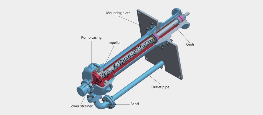
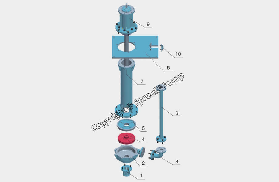
| 1 | Lower strainer | 2 | Pump casing | 3 | bend | 4 | Impeller | 5 | Guard plate |
|---|---|---|---|---|---|---|---|---|---|
| 6 | Outlet pipe | 7 | Supporting tube | 8 | Mounting tube | 9 | Bearing parts | 10 | Clamp |
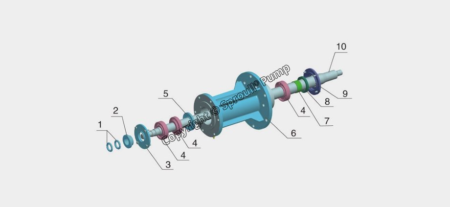
| 1 | Round nut | 2 | Labyrinth ring | 3 | Upper bearing end cover | 4 | Bearing | 5 | Oil retaining disk |
|---|---|---|---|---|---|---|---|---|---|
| 6 | Bearing body | 7 | Bearing spacer sleeve | 8 | Oil seal | 9 | Lower bearing end cover | 10 | Shaft |
Sproull® LYF Preformance Curve
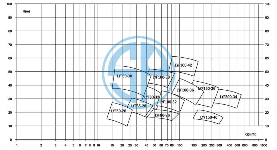
| lllustrations of Model Type | |||
|---|---|---|---|
| LYF150-35 | |||
| LYF | Vertical Mud Pump | ||
| 150 | Outlet Diameter (mm) | ||
| 35 | Impeller Diameter(mm) | ||
Sproull® LYF Preformance parameter list
| Type |
Speed n(r/min) |
Capacity Q(m³/h) |
Head H(m) |
Eff η(%) |
Motor power (kw) |
|---|---|---|---|---|---|
| LYF50-28 | 1440 | 15 | 27 | 41 | 4 |
| 20 | 25 | 42 | |||
| 25 | 23.7 | 45 | |||
| LYF65-28 | 970 | 12 | 23.6 | 41 | 11 |
| 24 | 22.2 | 42 | |||
| 30 | 21.3 | 45 | |||
| LYF80-32 | 1470 | 43 | 36 | 42 | 22 |
| 57 | 34 | 43 | |||
| 72 | 32 | 45 | |||
| LYF100-36 | 980 | 63.6 | 19.7 | 43.8 | 30 |
| 106 | 17.1 | 52 | |||
| 127 | 15.8 | 50.6 | |||
| LYF150-40 | 730 | 125 | 11.7 | 47 | 30 |
| 208.6 | 11.1 | 62 | |||
| 250.3 | 9.2 | 57 | |||
| LYF200-34 | 1480 | 276 | 38 | 59 | 90 |
| 460 | 35 | 69 | |||
| 552 | 33 | 64 | |||
|
Only part of the product model demonstration If the actual requirements of performance parameters and performance table does not match, can be based on user requirements for design and manufacture. |
|||||
Sproull® LYF Installation Drawing(Demonstration)
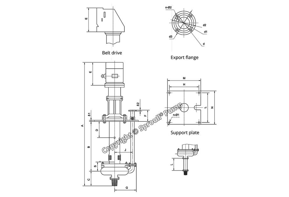
| Type | Installation Dimensions(mm) | |||||||||||||||||
|---|---|---|---|---|---|---|---|---|---|---|---|---|---|---|---|---|---|---|
| A | B | C | D | E | F | G | M*N | H*L | J | n-Φ1 | δ1 | Outler flange | ||||||
| d | d1 | d2 | d3 | n-Φ2 | δ2 | |||||||||||||
| LYF150-35 | 2828 | 1054 | 360 | 350 | 660 | 216 | 610 | 1150*900 | 1080*830 | 480 | 4-Φ25 | 20 | Φ15 | Φ200 | Φ225 | Φ260 | 8-Φ18 | 22 |
Capacity: 5.3~600 m³/h
Head: 6-40 m
Speed:730,1480 r/min
Working Temperature:≤105℃
Design features:
1. The full combination of new design concepts, advanced design methods, and solid-liquid two-phase flow theory optimizes the pump for high efficiency, long service life and reliable operation.
2. Different and reasonable configurations are adopted for the characteristics and needs of different users and different working conditions.
3. Rigid shaft design, large shaft diameter, stable operation, no shaft seal, reasonable structure and convenient maintenance.
4. The wetted parts are made of all-metal anti-wear white cast iron (KMTBCR27). The carbon element is mainly distributed in the metal matrix structure in the form of carbides, which has good anti-abrasive properties.
5. The all-metal pump design overcomes the shortcomings of non-metal pump linings that are easy to fall off, tear, and deform. The service life of the flow parts is long. The metal guard plate has a stronger ability to withstand shear sliding wear than general non-metal materials, and can withstand Long-term shear wear.
6. The geometric dimensions of the all-metal pump are easy to control and guarantee, the surface finish of the parts is high, the part matching gap is small, the volumetric efficiency is high, and the overall efficiency is more than 5% higher than that of the non-metal pump.
7. All flow parts adopt integral casting, resin sand modeling, and low hydraulic friction loss.
8. The bearings are lubricated with grease, and grease is added regularly according to the technical requirements, which can greatly extend the bearing
The service life of the component.

